Trace a requirement to a design decision
Write an evidence-linked DQ row that keeps later testing visible.
2.3 minutes · English captions · Illustrations and worked example
This lesson’s core explanations and worked-example reasoning are narrated. The table restates the example for reference; the practice activity and model answer are reading exercises.
English captions available.
Narration and visual explanations
Open View Technical Explanation to see each diagram, its text description and the matching narration. Standard abbreviations and numerals are used visually.
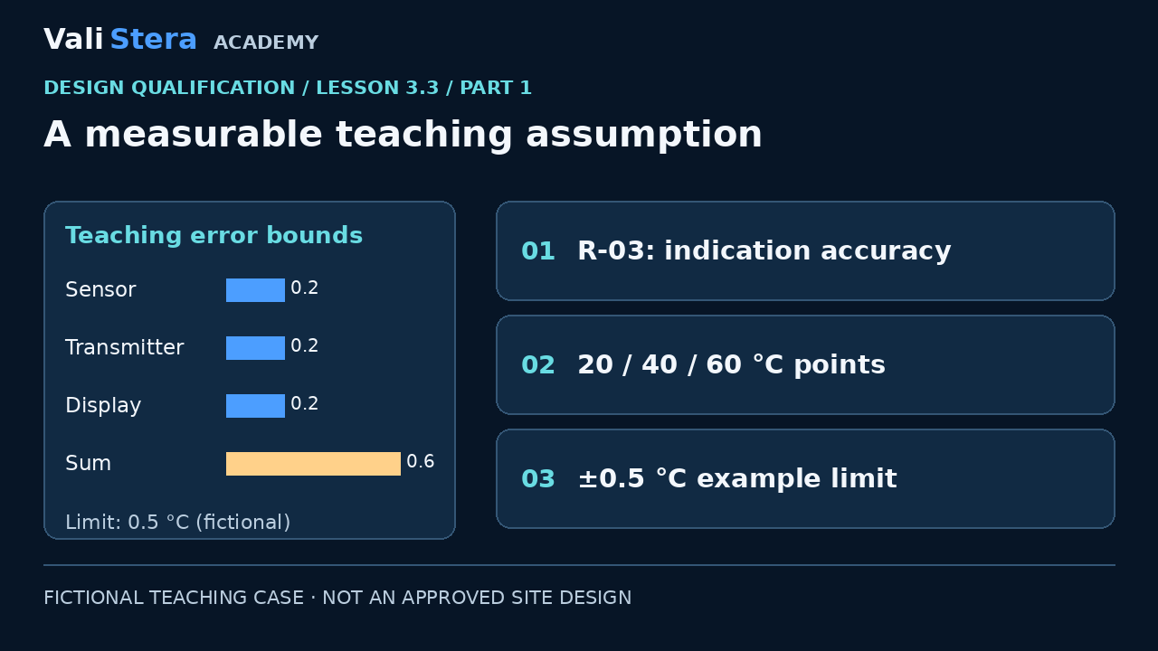
A measurable teaching assumption
View Technical Explanation · Diagram 1
Lesson explanation
For a separate worked example, assume a fictional process owner has approved temperature indication at 20, 40 and 60 °C with error no greater than ±0.5 °C. These are teaching assumptions, not general GMP tolerances or real project approvals. Requirement R-03 concerns indication accuracy. It does not establish product temperature uniformity, mixing performance or an acceptable manufacturing process range.
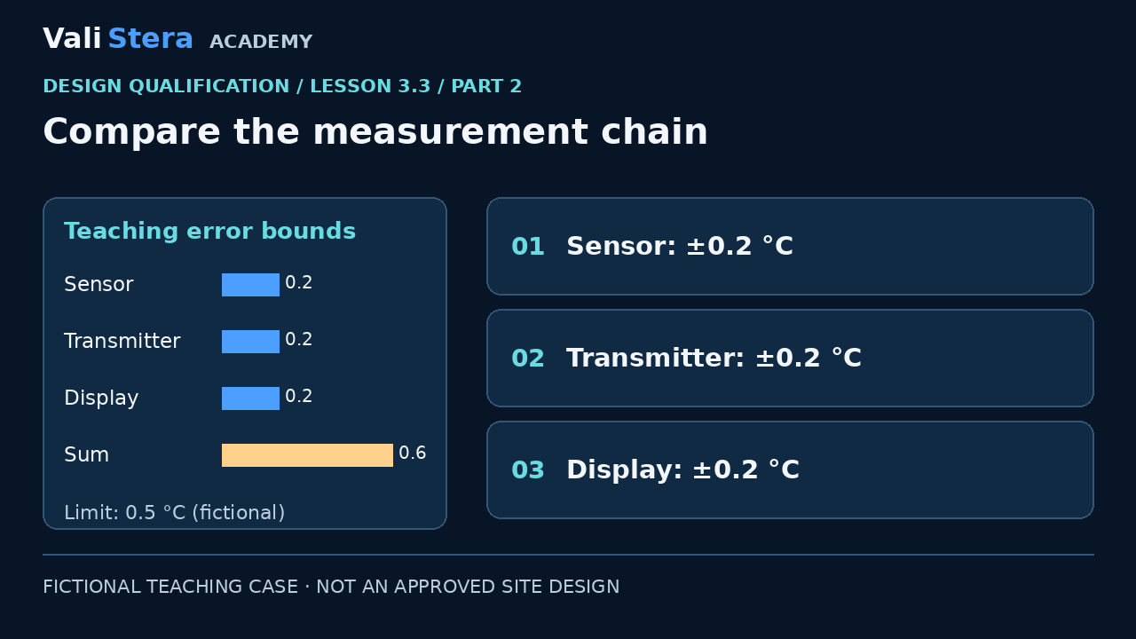
Compare the measurement chain
View Technical Explanation · Diagram 2
Lesson explanation
The supplier lists three component error bounds of ±0.2 °C each: sensor, transmitter and display. If they can all act in the same direction, the simple worst-case sum is 0.6 °C. That exceeds the worked requirement of 0.5. Calling each component accurate would miss the chain. This conservative teaching calculation is not a complete uncertainty budget or an automatic rejection of every possible design. Other combination methods exist, but their assumptions, correlations and intended decision must be justified by appropriate metrology expertise.
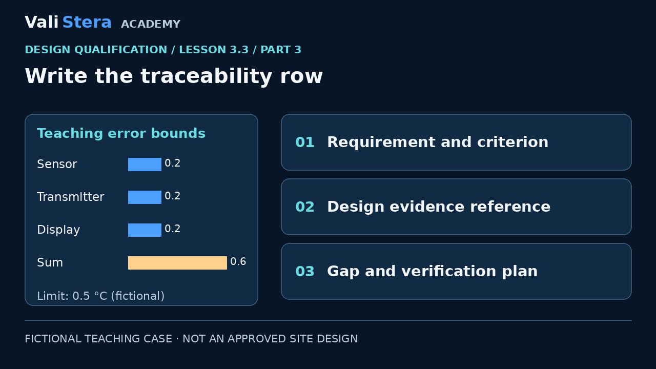
Write the traceability row
View Technical Explanation · Diagram 3
Lesson explanation
The row identifies R-03, the criterion, sensor schedule S-07 revision B and the calculation. Its decision is not demonstrated. The action is to propose a justified measurement-chain design or revise the requirement through authorized change, not quietly relax the criterion. Installation checks must confirm the selected components. Operational testing must challenge the assembled chain under the approved method. DQ plans this evidence; it does not invent its results.
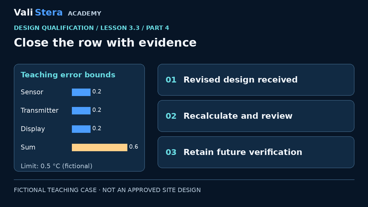
Close the row with evidence
View Technical Explanation · Diagram 4
Lesson explanation
Suppose the supplier proposes lower-error components. Review their applicable conditions and recalculate the chain; do not close the row merely because a new datasheet arrived. If the revised design supports the requirement, record the rationale and reviewer decision. Keep the later installation and operational checks in the verification plan. Distinguish design evidence adequate from installed performance demonstrated. The workbook contains a filled row and a blank row for practice.
Worked example
| Field | Filled teaching row |
|---|---|
| Requirement | R-03: indication error within ±0.5 °C at 20, 40, 60 °C (fictional approved assumption) |
| Evidence | S-07 rev B; three applicable component bounds of ±0.2 °C |
| Design review | Worst-case bound 0.6 °C; requirement not yet supported |
| Action | Supplier proposes suitable chain; metrology reviews applicability and decision rule |
| Later verification | IQ component identity; OQ assembled-chain challenge; results not yet available |
Explore the conservative error bound
Positive component bounds in °C; sum assumes aligned errors. Fictional requirement 0.50 °C. This arithmetic is not a full uncertainty budget.
Worst-case sum: 0.60 °C. Exceeds the fictional 0.50 °C requirement.
Apply it · Activity 3
Complete one DQ traceability row for R-03. Explain why three ±0.2 °C components do not automatically meet a ±0.5 °C chain requirement.
Open workbook activityCompare with model reasoning
Worst-case sum is 0.6 °C. Record the design gap, evidence reference and supplier action. Reassess revised components and retain installation/assembled-chain verification. Do not treat this sum as a full uncertainty budget.