Review utility and installation interfaces
Find design assumptions at boundaries before they become installation surprises.
2.0 minutes · English captions · Illustrations and worked example
This lesson’s core explanations and worked-example reasoning are narrated. The table restates the example for reference; the practice activity and model answer are reading exercises.
English captions available.
Narration and visual explanations
Open View Technical Explanation to see each diagram, its text description and the matching narration. Standard abbreviations and numerals are used visually.
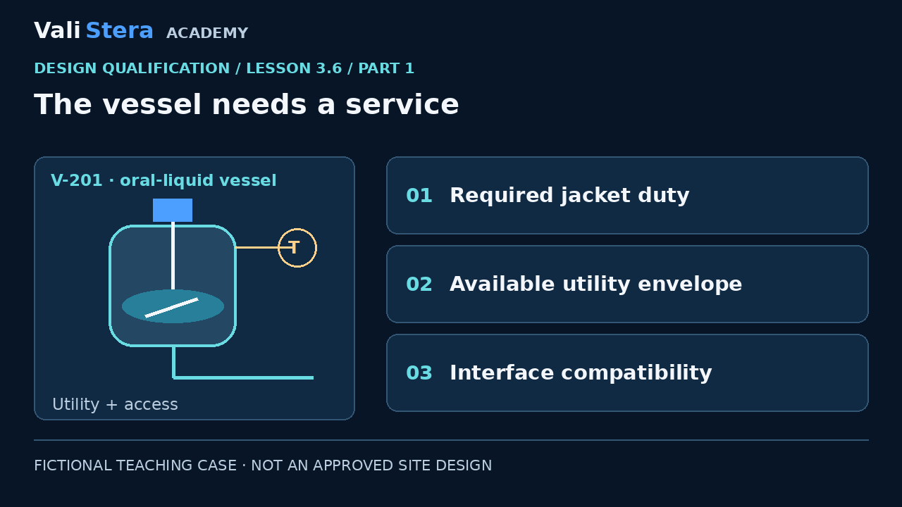
The vessel needs a service
View Technical Explanation · Diagram 1
Lesson explanation
The jacket is not useful simply because a utility pipe reaches the room. Compare the process need, the vessel design assumptions and the available utility envelope. Our fictional process duty remains a controlled input rather than an invented number. Consider flow, temperature, pressure and capacity under relevant conditions, using appropriate engineering expertise. A utility qualification report and a vessel design review answer different questions; their interface still needs a compatibility assessment.
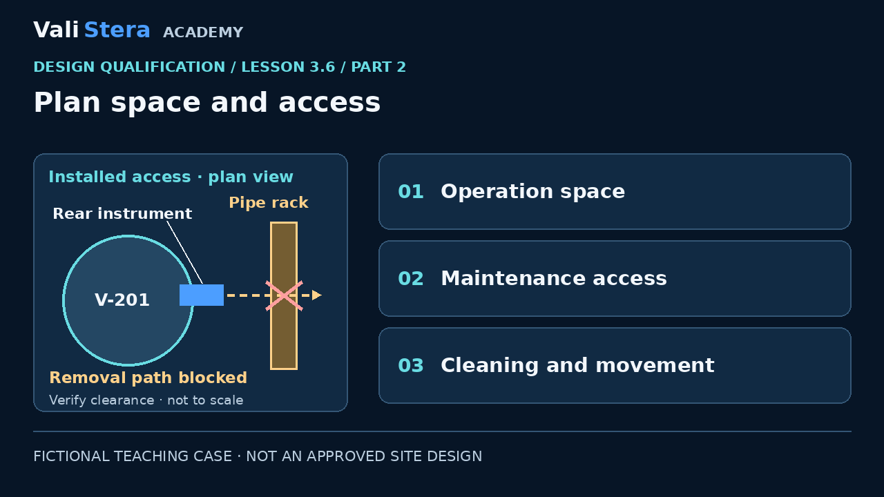
Plan space and access
View Technical Explanation · Diagram 2
Lesson explanation
An arrangement drawing should support safe and practical operation, cleaning, inspection and maintenance within the applicable facility design. Our sketch places an instrument behind a vessel where removal may be blocked. Ask whether the required access exists after piping and adjacent equipment are installed. Do not treat empty space on a two-dimensional drawing as proof of access. Engineering checks, dimensions or a suitable model may be needed.
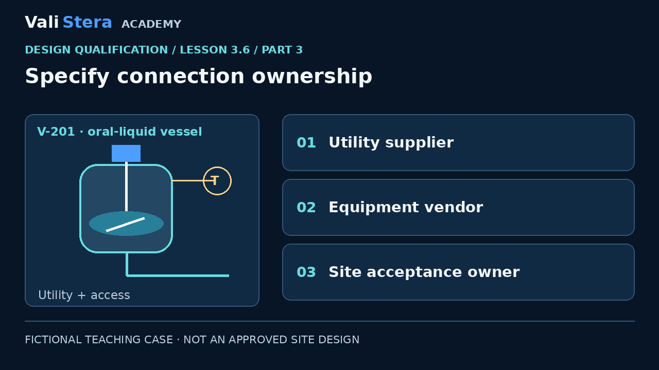
Specify connection ownership
View Technical Explanation · Diagram 3
Lesson explanation
A boundary can divide contracts without dividing the technical risk. Record who supplies the connector, who defines its rating, who confirms compatibility and who accepts the interface evidence. The fictional register assigns utility conditions to site engineering and connection details to the vendor, with a joint compatibility review. This prevents a gap where each party assumes the other has checked the connection. Responsibilities should match the site’s actual organization.
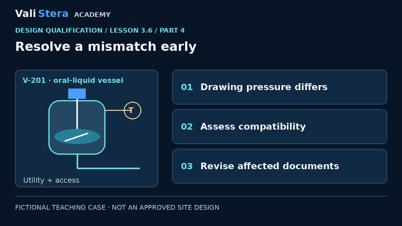
Resolve a mismatch early
View Technical Explanation · Diagram 4
Lesson explanation
Suppose the utility schedule and vendor drawing show different pressure assumptions. Stop treating the interface as resolved. Determine which values are correct and assess the effect on design, protective measures and future tests. Do not choose the higher number merely to make the documents agree. A controlled technical decision should update the affected records and retain traceability to the requirement and design basis.
Worked example
| Interface | Evidence owners | Open question |
|---|---|---|
| Jacket supply | Site utility engineer + vessel vendor | Do supply envelope and vessel rating/duty agree? |
| Instrument access | Layout engineer + maintenance | Can the instrument be removed in the installed arrangement? |
| Transfer connector | Vendor + operations/cleaning | Are connection, material and cleaning assumptions compatible? |
Apply it · Activity 6
Fill an interface register for jacket utility, instrument access and transfer connection.
Open workbook activityCompare with model reasoning
For each interface record required input, design evidence, supplying owner, accepting owner, mismatch and action. Do not replace missing duty/rating data with catalogue values.