Review instruments, controls and failure responses
Evaluate the design of control protection without assuming two displays mean independence.
2.4 minutes · English captions · Illustrations and worked example
This lesson’s core explanations and worked-example reasoning are narrated. The table restates the example for reference; the practice activity and model answer are reading exercises.
English captions available.
Narration and visual explanations
Open View Technical Explanation to see each diagram, its text description and the matching narration. Standard abbreviations and numerals are used visually.
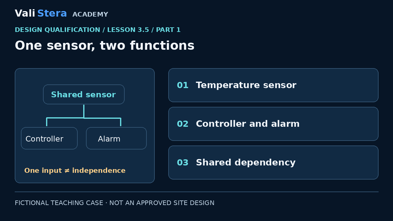
One sensor, two functions
View Technical Explanation · Diagram 1
Lesson explanation
A temperature sensor feeds both the controller and the high-temperature alarm. The diagram branches one signal into two functions. Two boxes on the drawing do not make two independent measurements. If the sensor fails low, both functions may receive the same misleading value. Whether that matters depends on the process risk and other protections. State the failure mechanism before deciding whether an independent sensor or another protective measure is necessary.
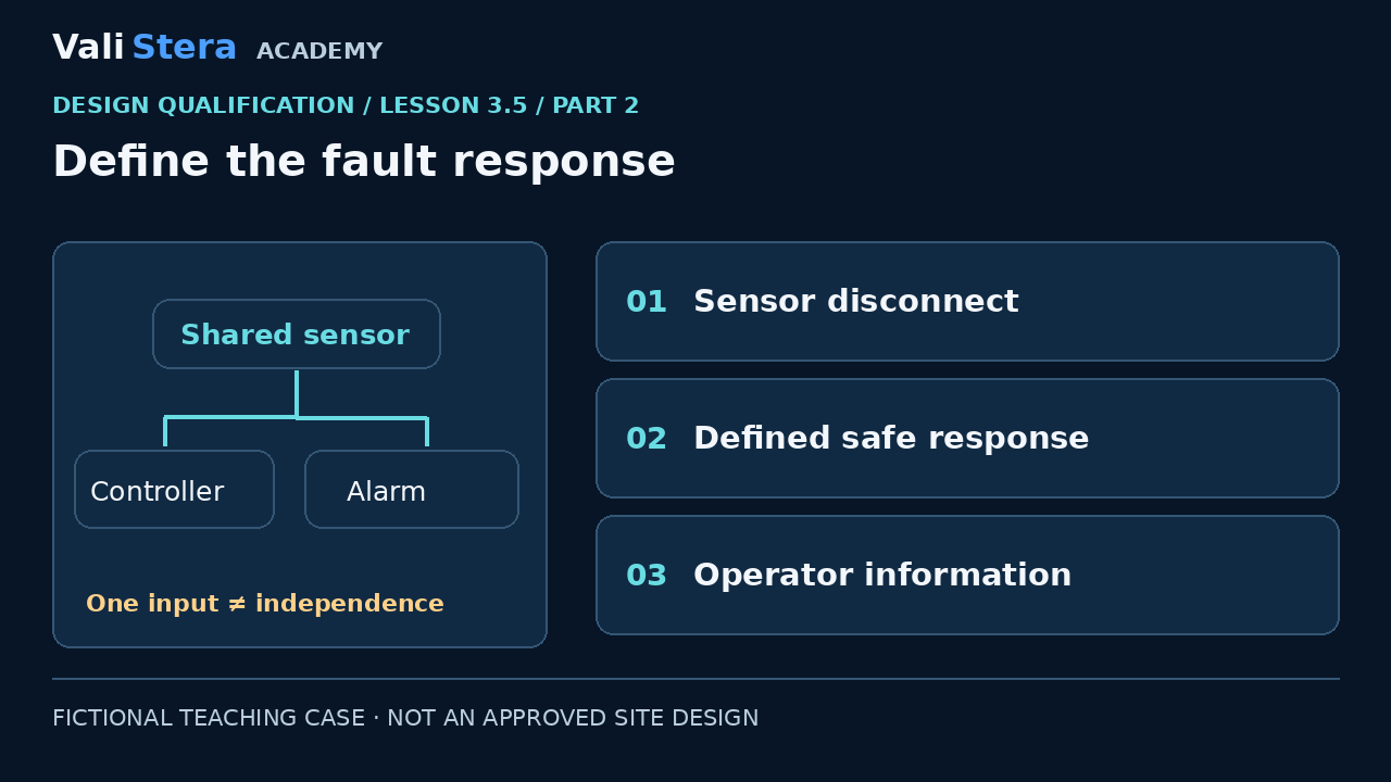
Define the fault response
View Technical Explanation · Diagram 2
Lesson explanation
The functional specification should describe the response to a detected sensor disconnect, including control behaviour and operator information appropriate to the intended use. Our teaching example proposes inhibiting heating and generating an identifiable alarm; it is not a universal safe-state instruction. Review whether that response introduces another hazard for the particular process. Distinguish an alarm that merely informs an operator from an interlock that changes operation automatically.
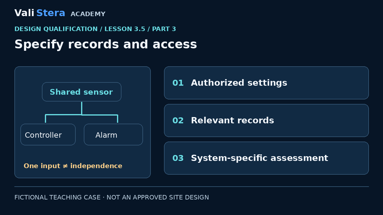
Specify records and access
View Technical Explanation · Diagram 3
Lesson explanation
If the control system creates records used for GMP decisions, identify those records and the applicable computerized-system requirements. Consider who can change a setpoint, how changes are controlled and how necessary records remain available. The European context is EU GMP Annex 11. Where relevant, also assess the applicability of FDA 21 CFR Part 11. This module flags the interface; it does not complete computerized-system validation or demonstrate compliance with either framework. A password screen by itself is not evidence of adequate access control, data integrity or record retention.
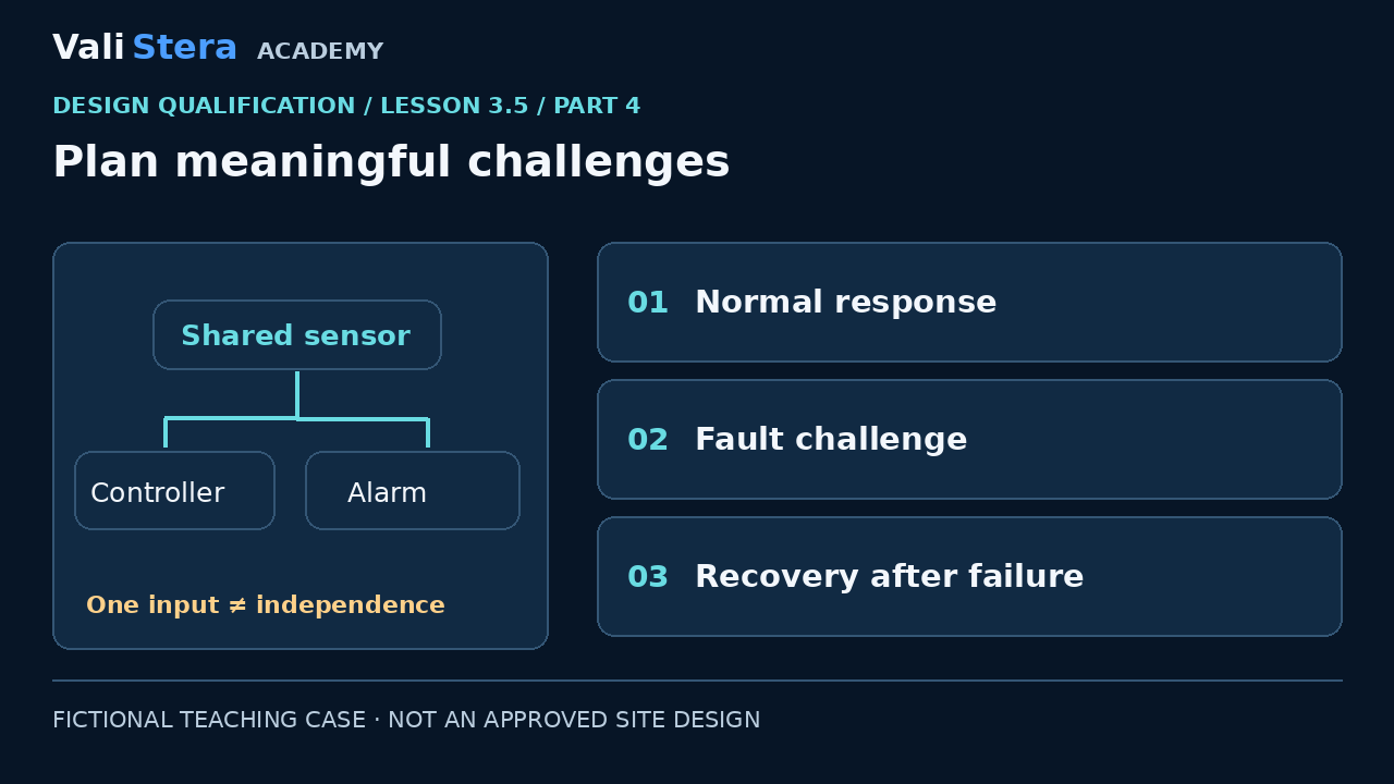
Plan meaningful challenges
View Technical Explanation · Diagram 4
Lesson explanation
Create a test intention for normal operation, the identified fault and recovery. For our sensor scenario, a later test should challenge the fault in a controlled way and verify the specified response and operator indication. Also consider restoration: an uncontrolled restart may be unacceptable. During DQ, check that the design and test method make the challenge feasible. The actual execution, safety controls and acceptance decision belong to approved site procedures.
Worked example
| Item | Fictional design-review entry |
|---|---|
| Failure | Sensor disconnect; assess additionally plausible undetected failures |
| Proposed response | Heating inhibited and alarm generated, subject to process-specific review |
| Evidence needed | Functional specification and wiring/signal architecture |
| Future test | Controlled fault challenge plus recovery/reset verification |
| Boundary | No claim of complete CSV or certified fail-safe design |
Apply it · Activity 5
Draw a shared-sensor chain and write a test intention for its failure response and recovery.
Open workbook activityCompare with model reasoning
Show the common sensor feeding both functions. Identify the fault, intended safe response, alarm information and reset/restart behaviour. Assess independence according to risk; do not demand it universally.